Purchase your kit here from the Garage Material Store and pick it up at the Garage!
Introduction
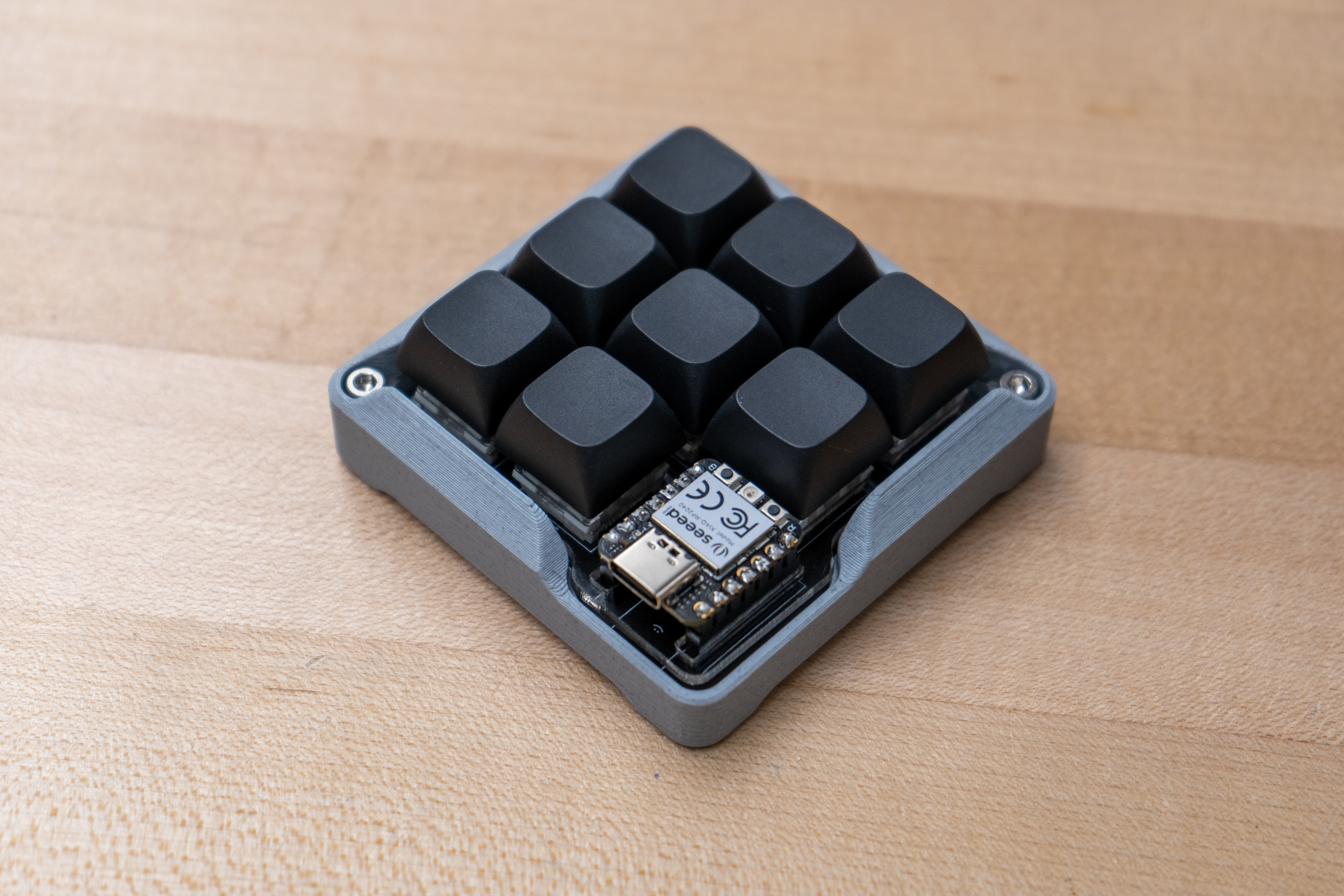
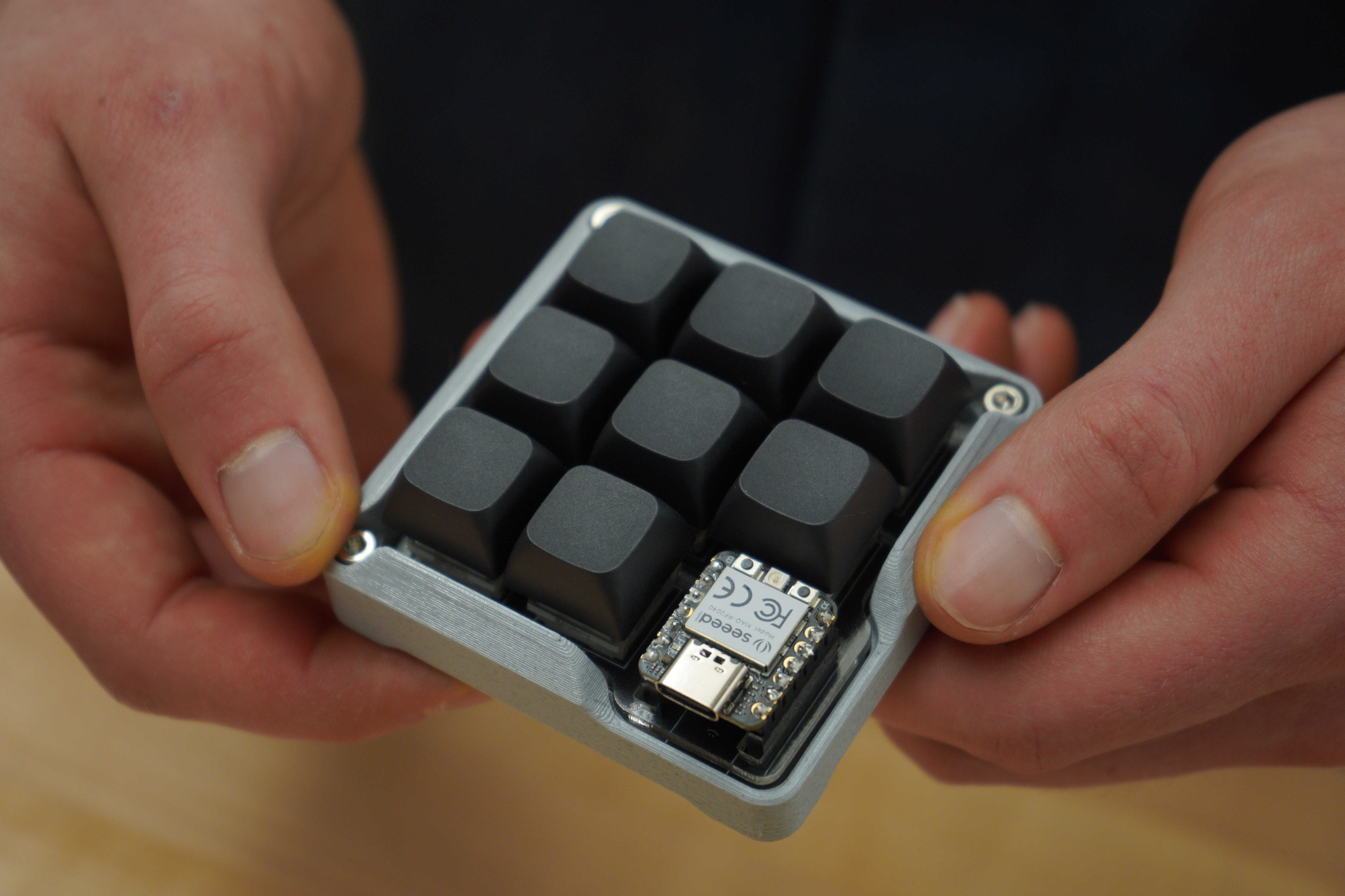
Hey there! Welcome to the inaugural edition of our new project kit series. The idea behind this document is to help you become more comfortable using the tools in the Elko Engineering Garage. We'll provide the project idea and a kit of parts - all you have to do is bring your willingness to learn. This project is a programmable macro-pad, with fancy mechanical key-switches and a cool 3D-printed case. You can rebind each of the keys to whatever function you want; use them for macros or shortcuts in your favorite software. This guide will walk you through 3D-printing, soldering, and laser-cutting all of the parts not included in the parts kit. A final thing to remember: this project is yours; feel free to make modifications or do thing differently to make it your own. The garage staff are happy to give you pointers if you get stuck - Just remember that you learn more when you make an effort to figure things out yourself.
Have Fun!
Required Equipment Trainings
You'll need to complete the training sessions for the following equipment before starting work on this project:
- Desktop FDM 3D Printer
- CO2 Laser Cutter
- Soldering Iron
Each of these training sessions are one hour in length. Note that a hybrid (online and in-person) option is currently offered for the 3D printer and CO2 laser cutter trainings.
Bill of Materials
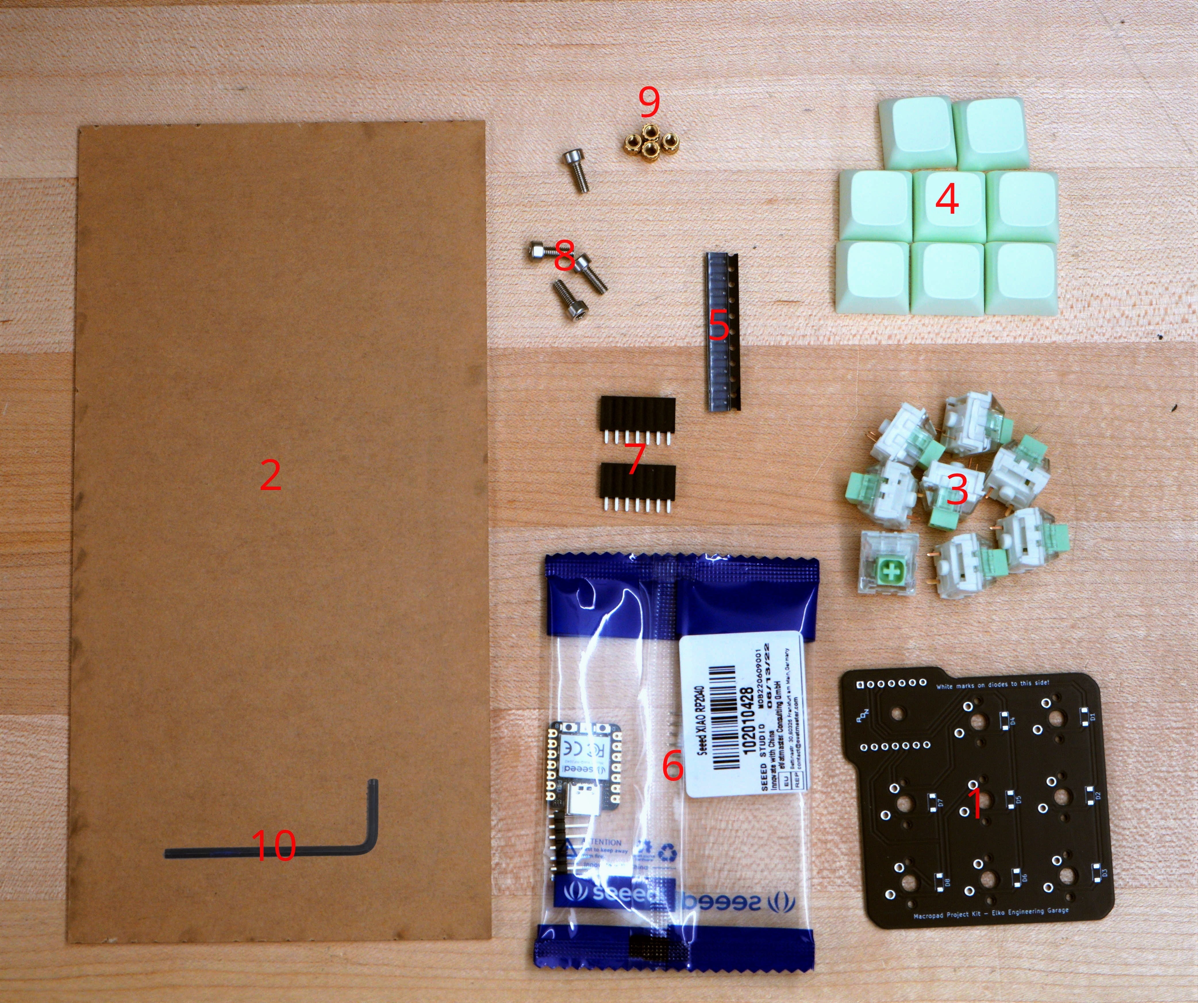
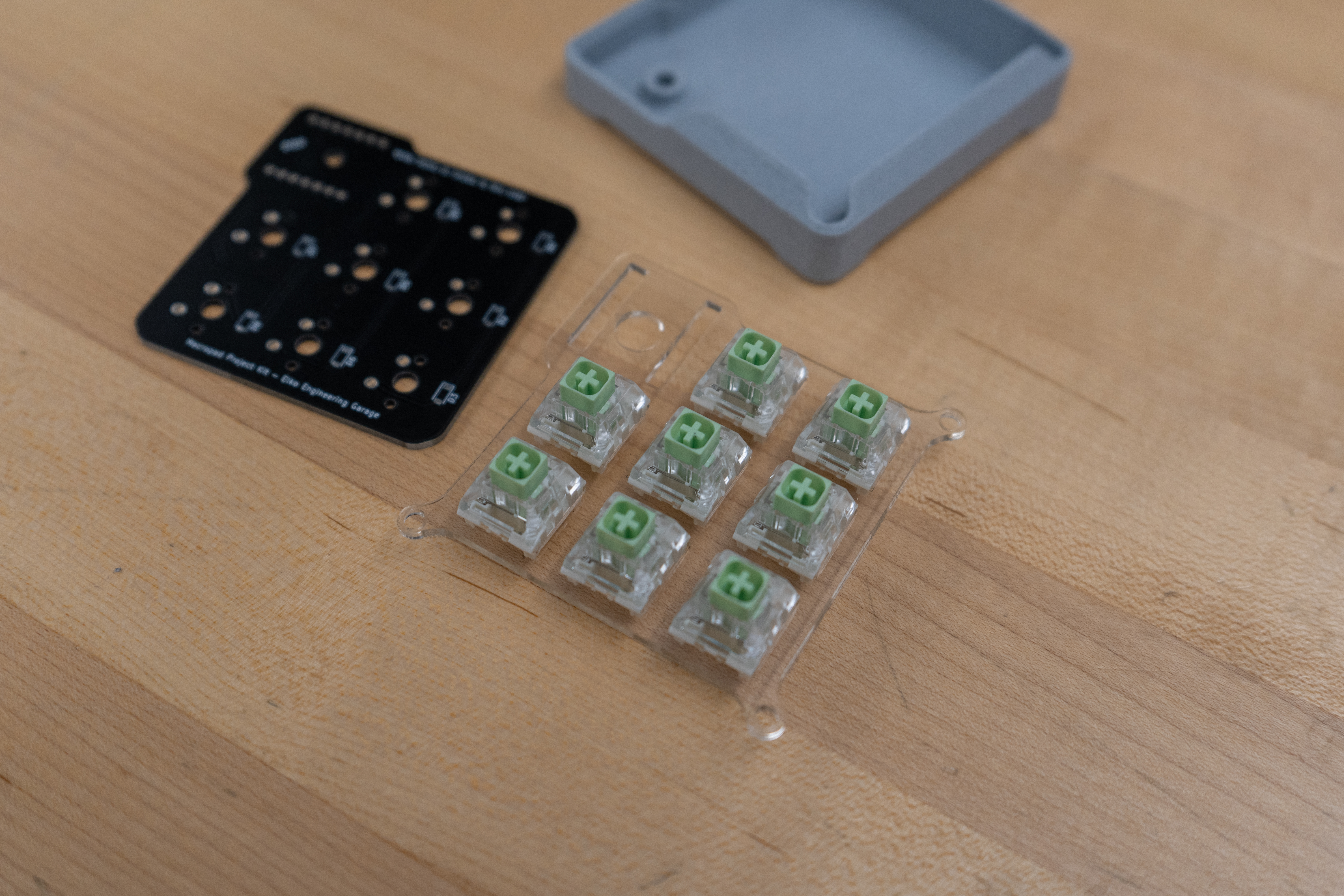
Make sure your project kit has all of the following:
| Item Name | Quantity | |
|---|---|---|
| 1 | Macro-pad printed circuit board | 1 |
| 2 | Piece of acrylic sheet - 4"x8"x1/16" | 1 |
| 3 | Key switch | 8 |
| 4 | Key cap | 8 |
| 5 | Diode | 10 |
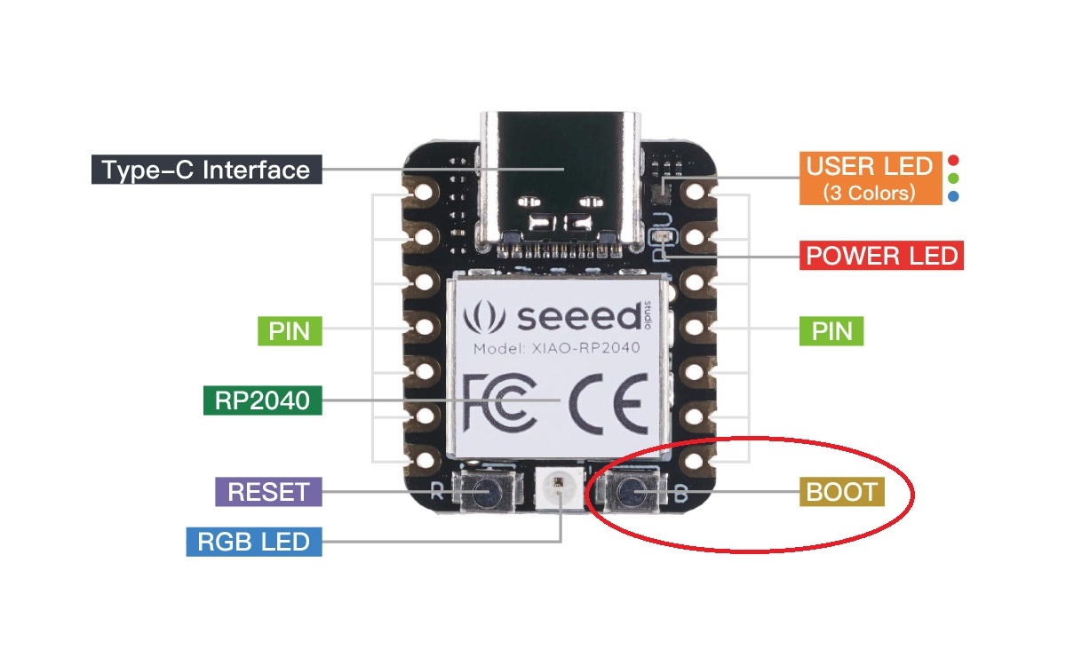
| 6 | Seeed Xiao RP2040 micro-controller with included pin headers | 1 |
| 7 | 7 row 0.1" pitch solder-able pin socket connector | 2 |
| 8 | M3x8mm socket head cap screw | 4 |
| 9 | Brass threaded insert | 4 |
| 10 | 2.5mm hex key | 1 |
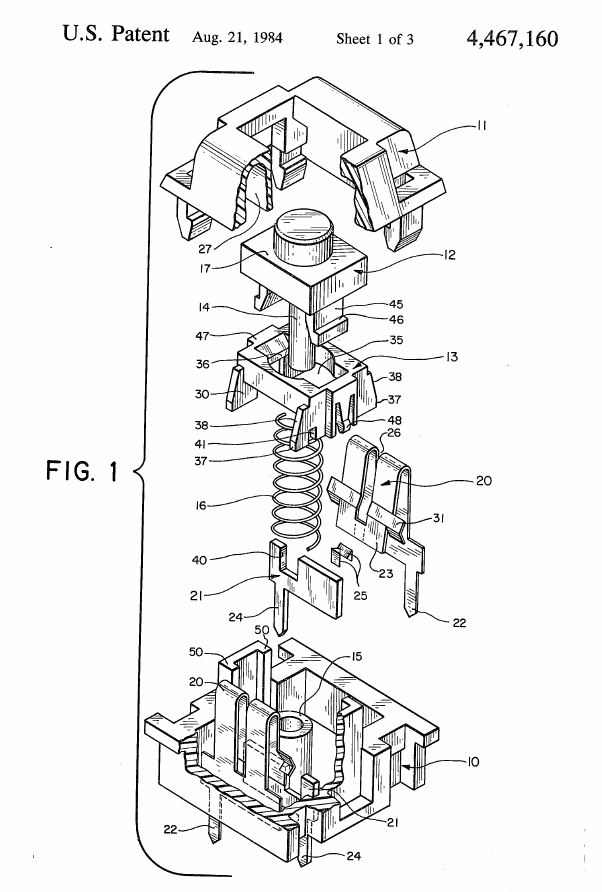
Key Switch Info
The switches in this kit follow a standard form factor for use with keyboards and other input devices. the kit comes with switches that make a noticeable click sound, and require a moderate amount of force to actuate. Many different brands and styles of compatible switches are available, so you can order your own to replace the ones in the kit if you want! (Check out this article for a more in-depth look at keyboard switch types)
Step 1: 3D-print the case
Time to complete: 10-30 minutes for print setup, plus about 2 hours of print time.
For this project, we'll print the housing (or case) out of PLA plastic. The Garage typically stocks 10-15 different colors of this material, so you can pick a style that compliments or contrasts with the other parts of the project. Begin by downloading the 3D model of the case and loading it into your preferred slicing software. (We recommend PrusaSlicer if you’re using a Prusa 3D printer)
This isn't a mechanical part, so the print settings don't have to be precisely tuned. For your reference, here are some settings that usually work well:
Parameter | Value |
Layer Height | 0.2 mm |
Shell Thickness | 0.8 mm |
Infill | 20% |
Extra Info
PLA is the most common type of 3D printing filament. It's typically made in a refining process that starts with fermented corn. It has a low melting point, which makes it easy to print. Mechanical properties vary by brand and print settings, but you usually won't be able to expect high durability and a long service from this material. That said, it does make usable prototypes quickly and inexpensively. It's also available in a wide range of nice colors!
Step 2: Laser-cut the plate
Time to complete: 10-45 minutes for setup and cutting.
This design uses an acrylic plate to hold the electrical components inside the case. We'll cut it out of 1/16" (1.59 mm) cast acrylic sheet. Begin by downloading the following file with the plate cut pattern:
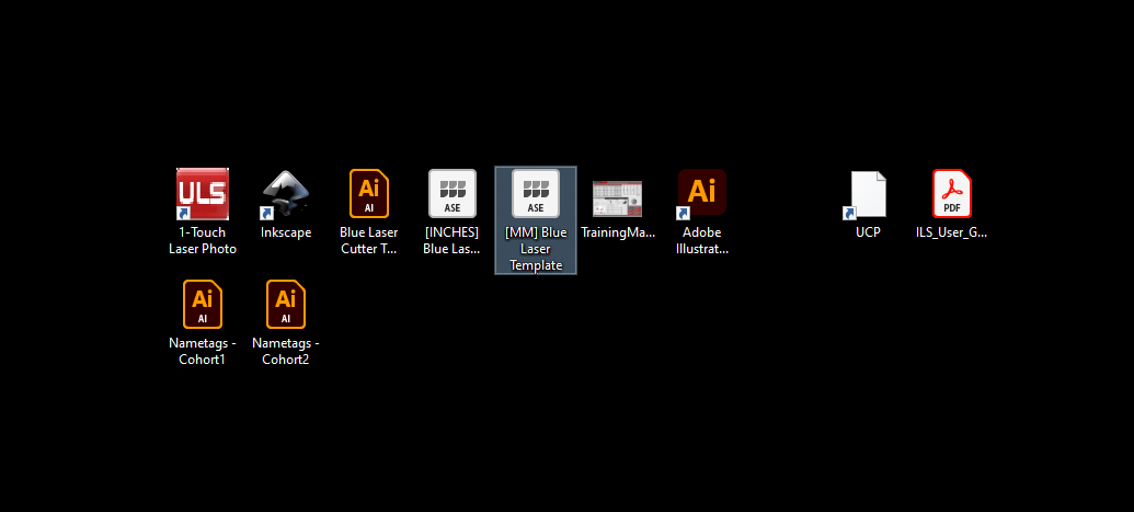
Open the laser cutter template file (named '[MM] Blue/Red Laser Template, located on the desktop of the laser cutter workstation) in Adobe Illustrator.
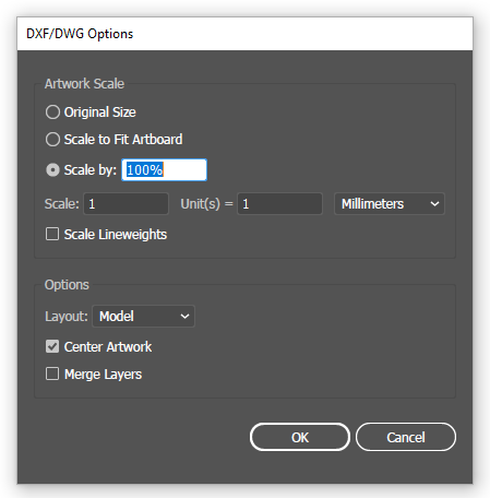
In another Illustrator tab, open the plate file. Make sure to import the file with the 'Scale by: 100%' option checked, and set the scale to '1 unit(s) = 1 Millimeters':
Press Ctrl+A to select all of the plate geometry, then press Ctrl+C to copy the plate. Switch back to the laser cutter template tab, then press Ctrl+V to paste the geometry into the template file.
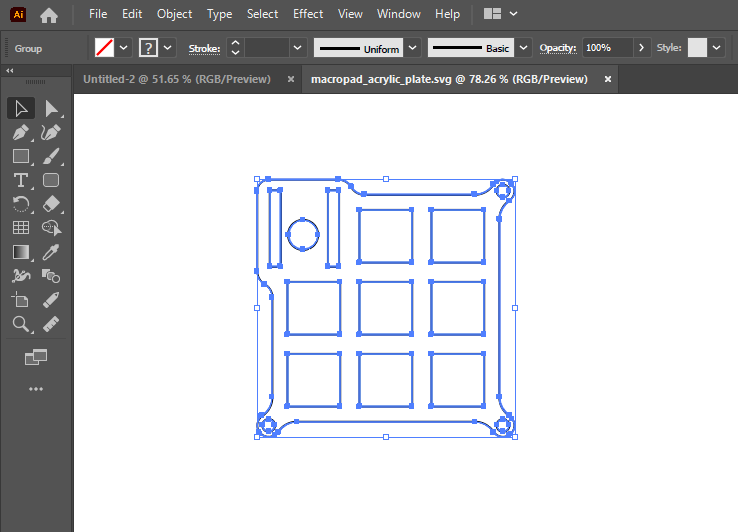
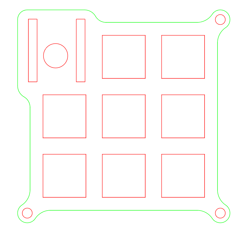
Change the line-width of all the visible geometry to 0.001 pt. The laser cutters will cut and engrave geometry in order based on the colors of objects. Change the outer profile to be green (RGB: 0, 255, 0) and make all of the inner features red (RGB: 255, 0, 0). Make sure that your file looks similar to the following screenshot:
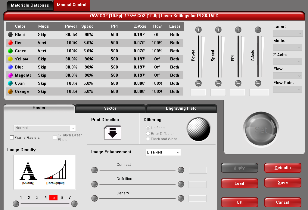
To change the print settings in Illustrator, click on print (or press Ctrl+P), then make sure that the 'ILS' (red laser cutter) or 'PLS' (blue laser cutter) printer type is selected. Then, click on Setup, and then Settings. This will open a menu where you can change the laser parameters. Select the red and green rows of the cut settings table, and change the process type to 'Vector'. Then, use the material selector to change the cut settings to Cast Acrylic, and the material thickness to 0.07" (1.8 mm). When you are happy with the print settings, click print to send the job to the machine.
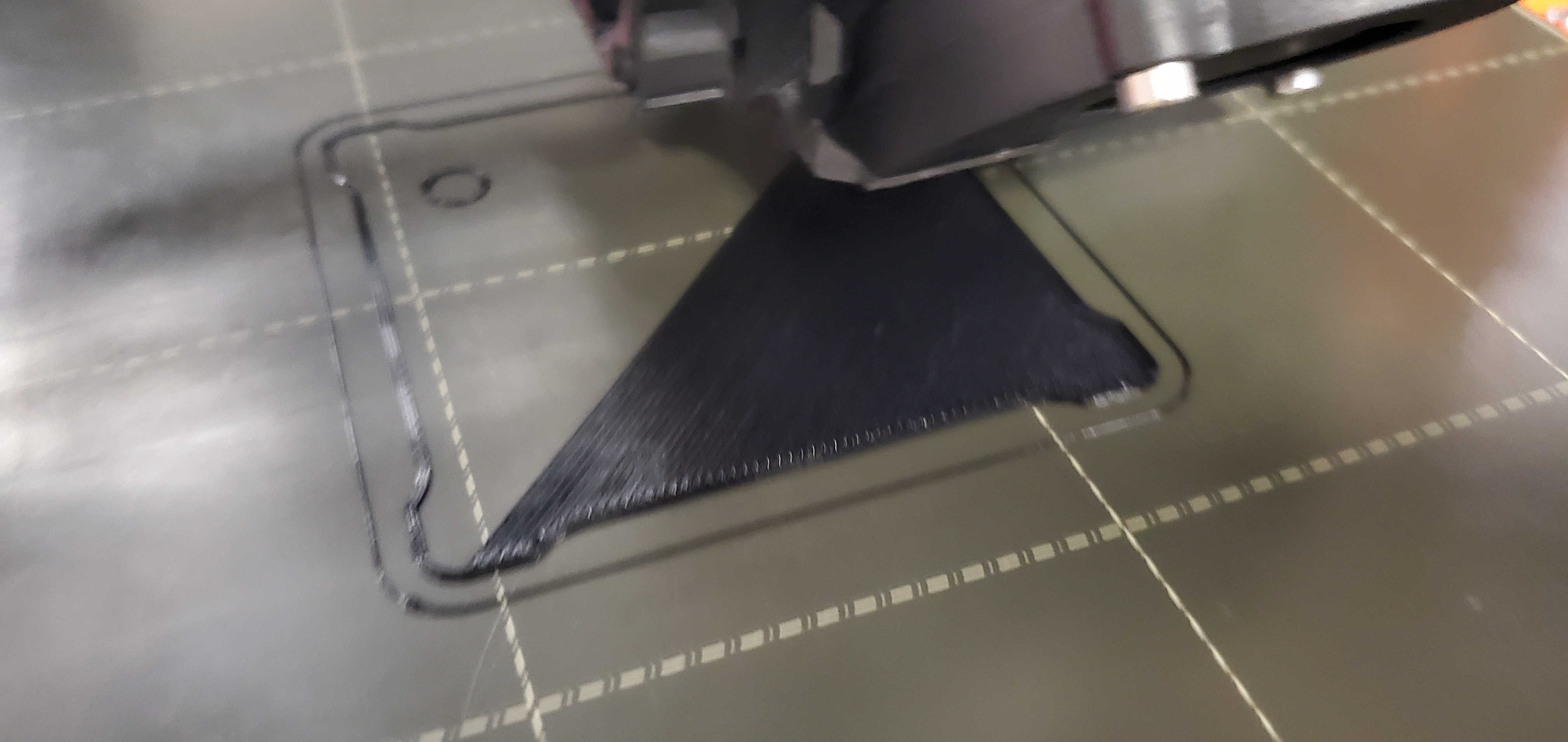
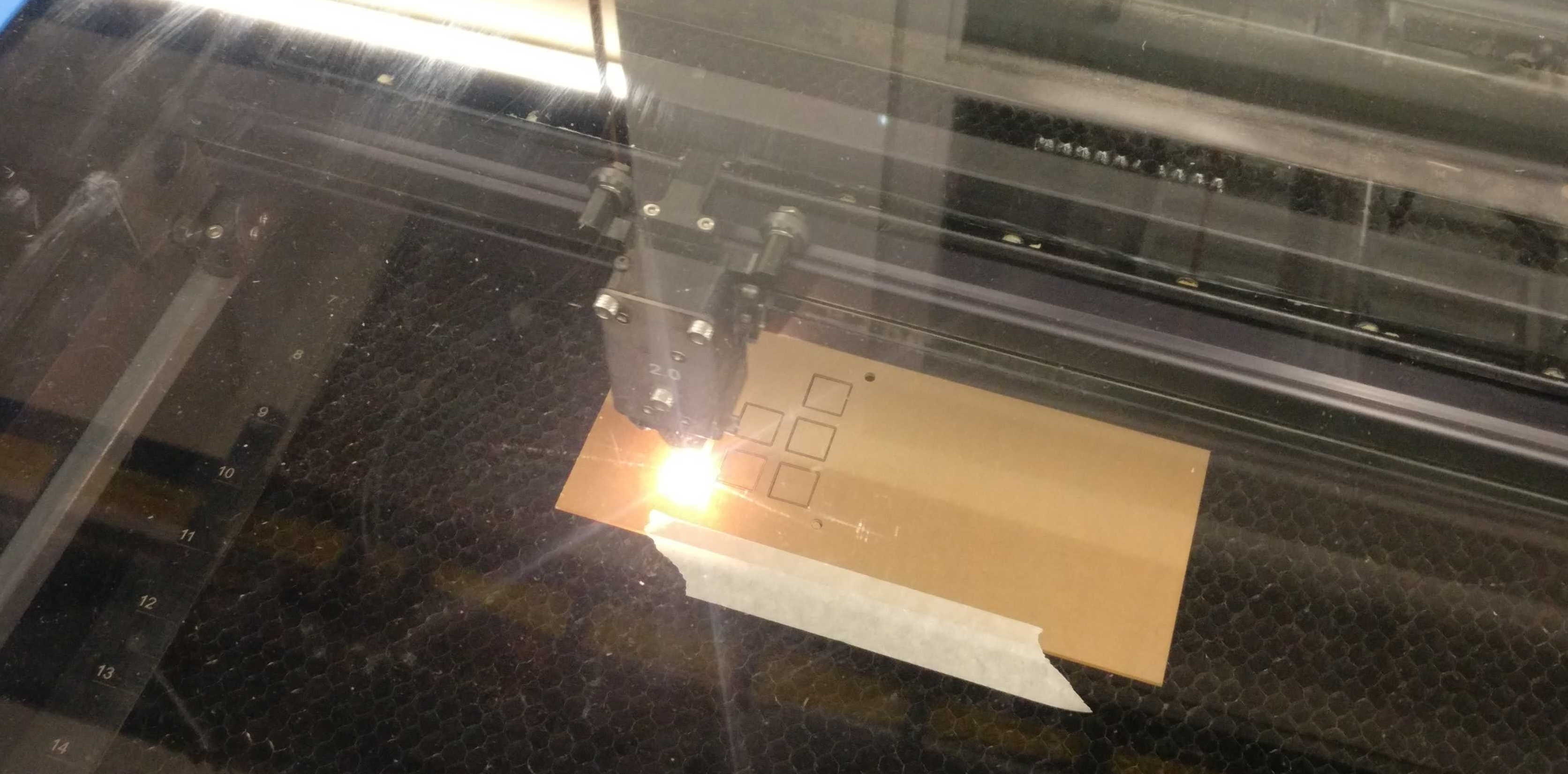
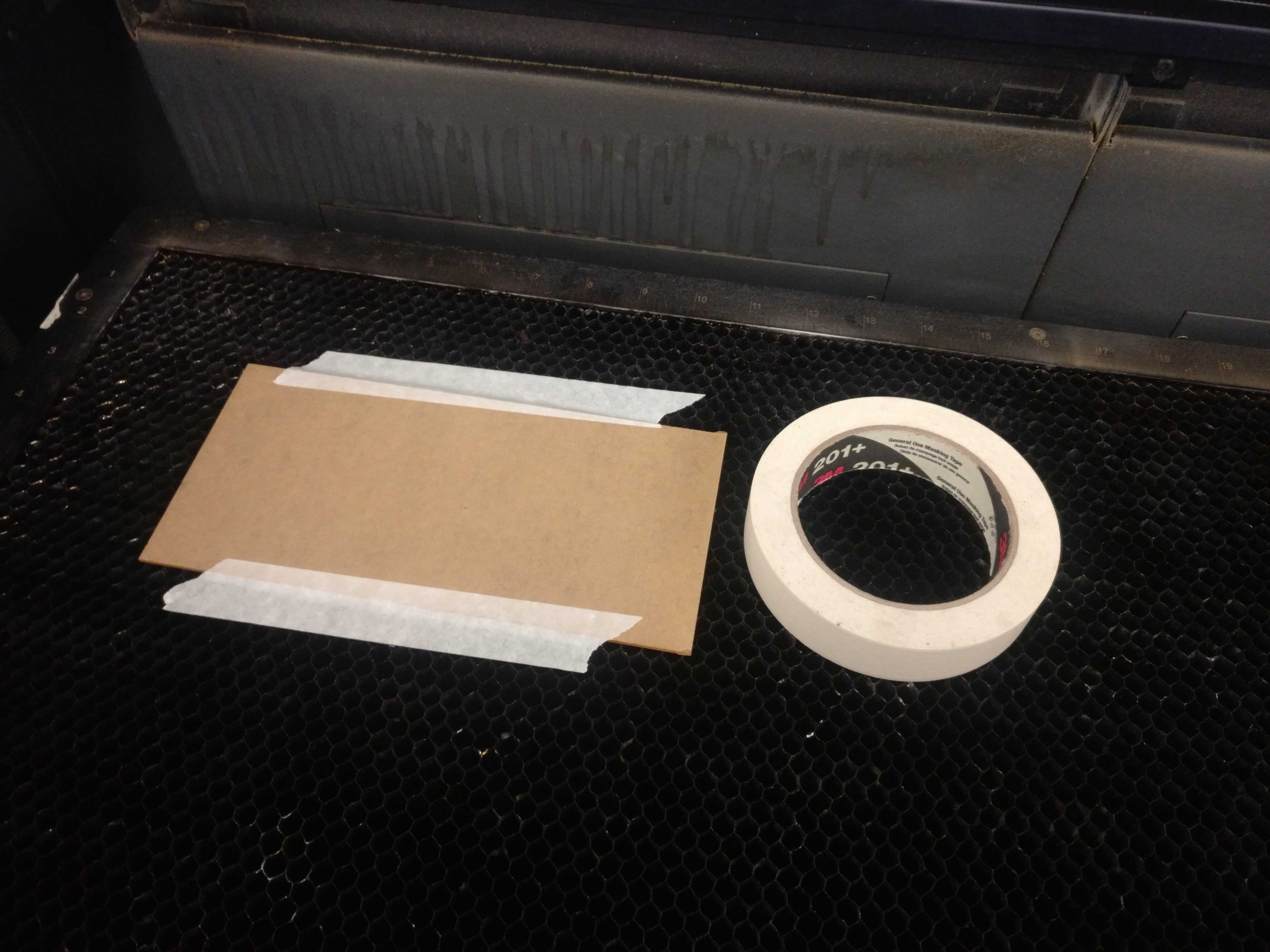
Open the UCP laser control software and home the machine if needed. You'll also need to set up your piece of stock inside the laser cutter. a 100x200mm sheet of acrylic is included with every project kit, so there's enough space for a second attempt if you get the settings wrong the first time. Use a bit of masking tape along the edges of the sheet to ensure that it doesn't shift during the cutting operation.
Note
Leave the protective paper or plastic film on during the cutting process. If you peel it off beforehand, the parts will tend to pick up some scratches and burn marks during cutting!
Use the focus view feature to ensure that the part will actually be cut from the right part of the sheet. When you're happy, hit run, and you should get a finished part in only a minute or two.
Extra Info
Acrylic is a good first choice for plastic parts. It's rigid, inexpensive, and available in all common sizes of sheets, rods, and tubes. you can laser-cut it, as well as drill and saw it with normal woodworking tools. Acrylic can be bonded with Cyanoacrylate glue (A.K.A. super glue). If you plan on purchasing some of this stuff for your own projects, make sure to get cast acrylic, rather than extruded acrylic. Cast material is much easier to work with, especially when using a laser cutter.
Step 3: Soldering and assembly
Time to complete: 20 minutes to 1 hour, depending on your soldering experience.
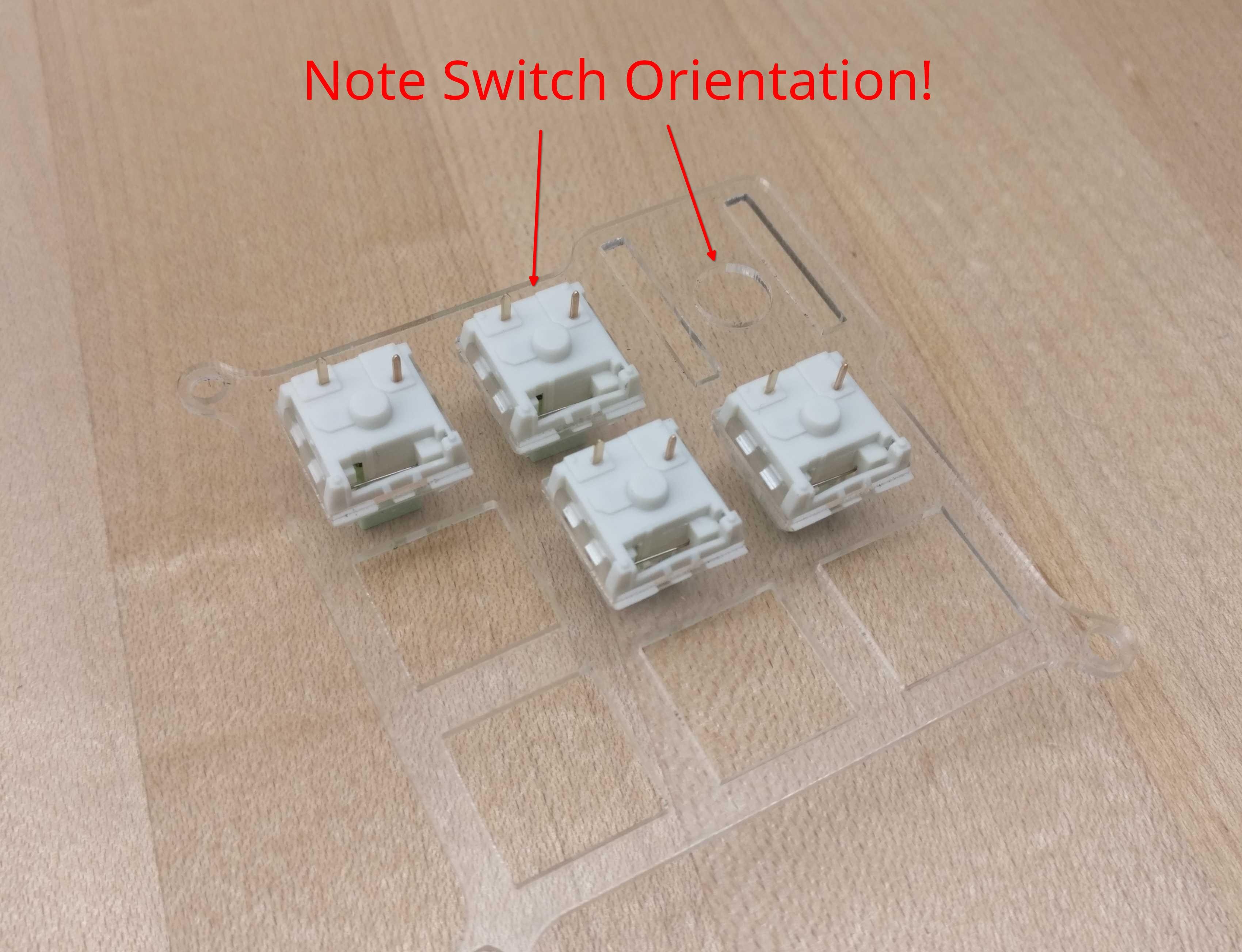
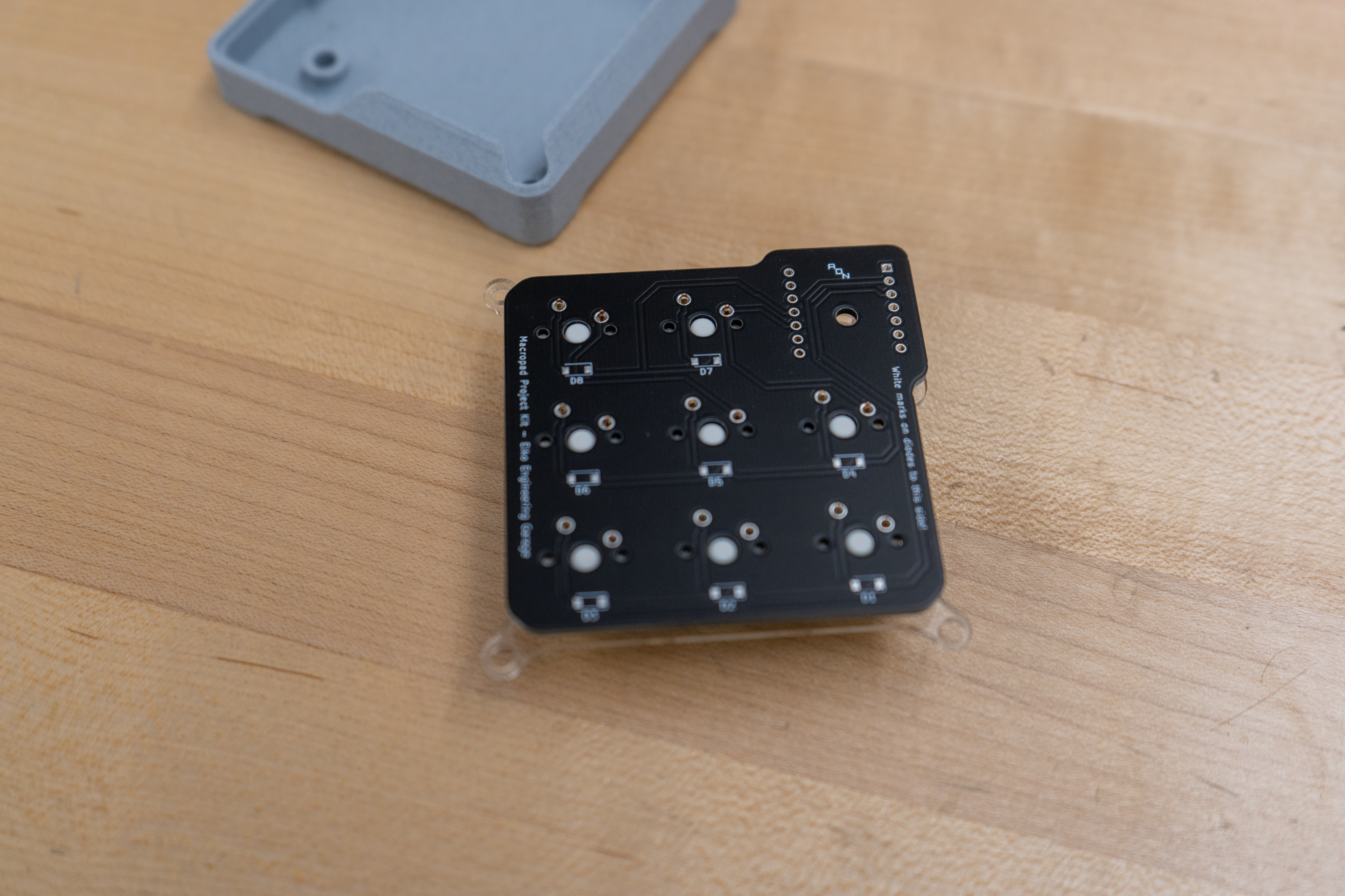
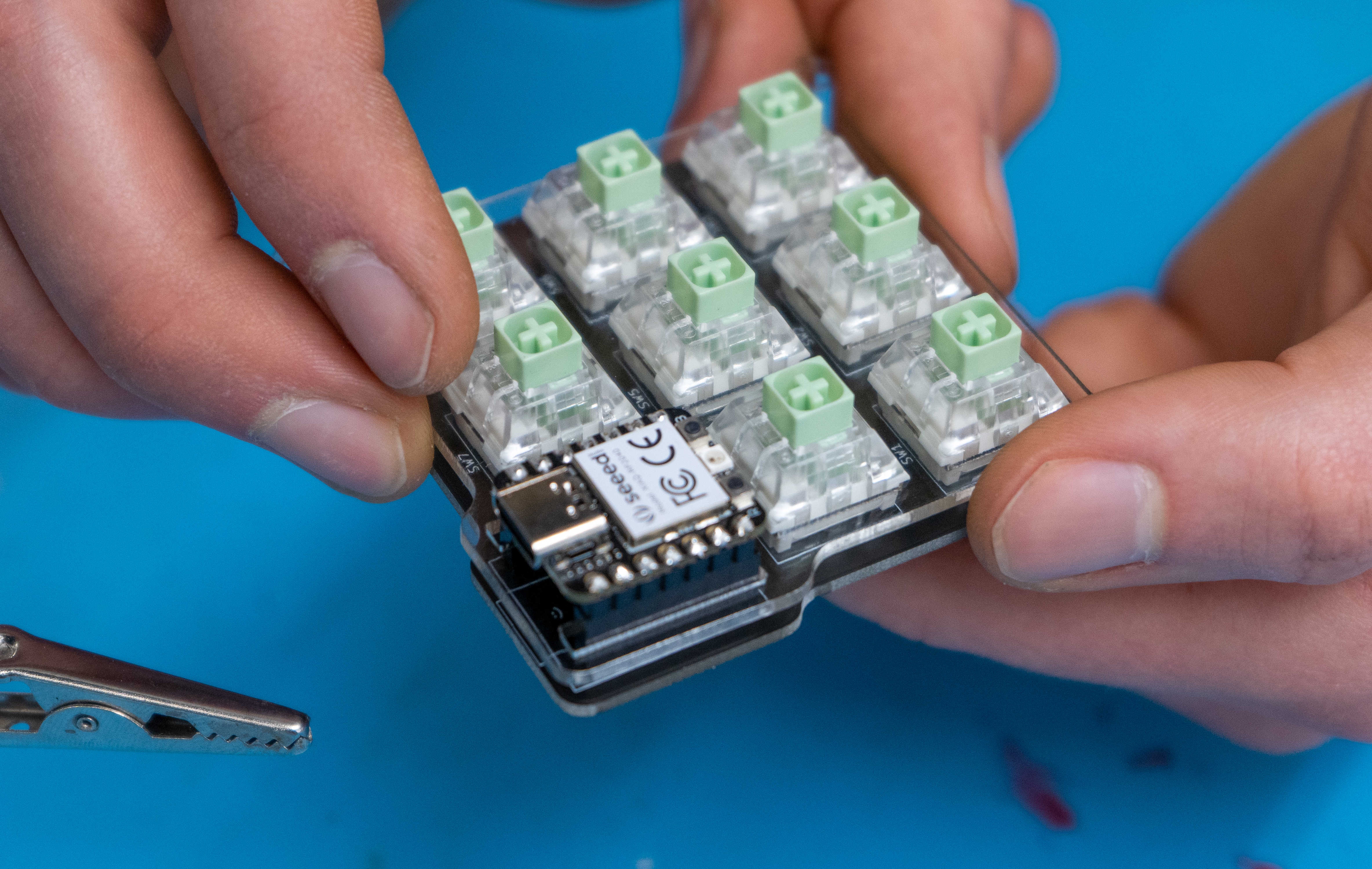
At this point, you should have a case and an acrylic plate. Let's get it all assembled! First, press the switches through their matching holes in the acrylic plate. Make sure to remove the protective film from the acrylic before adding the switches. The holes are square, so you'll need to get each switch in the correct orientation.
Once the switches are firmly seated in their correct locations, firmly press the PCB onto the plate-switch assembly. It should take a bit of force, since the pins molded into the switch housings are a press fit with the holes in the PCB. Make sure that all of the switches are fully seated and sitting correctly on the top surface of the PCB.
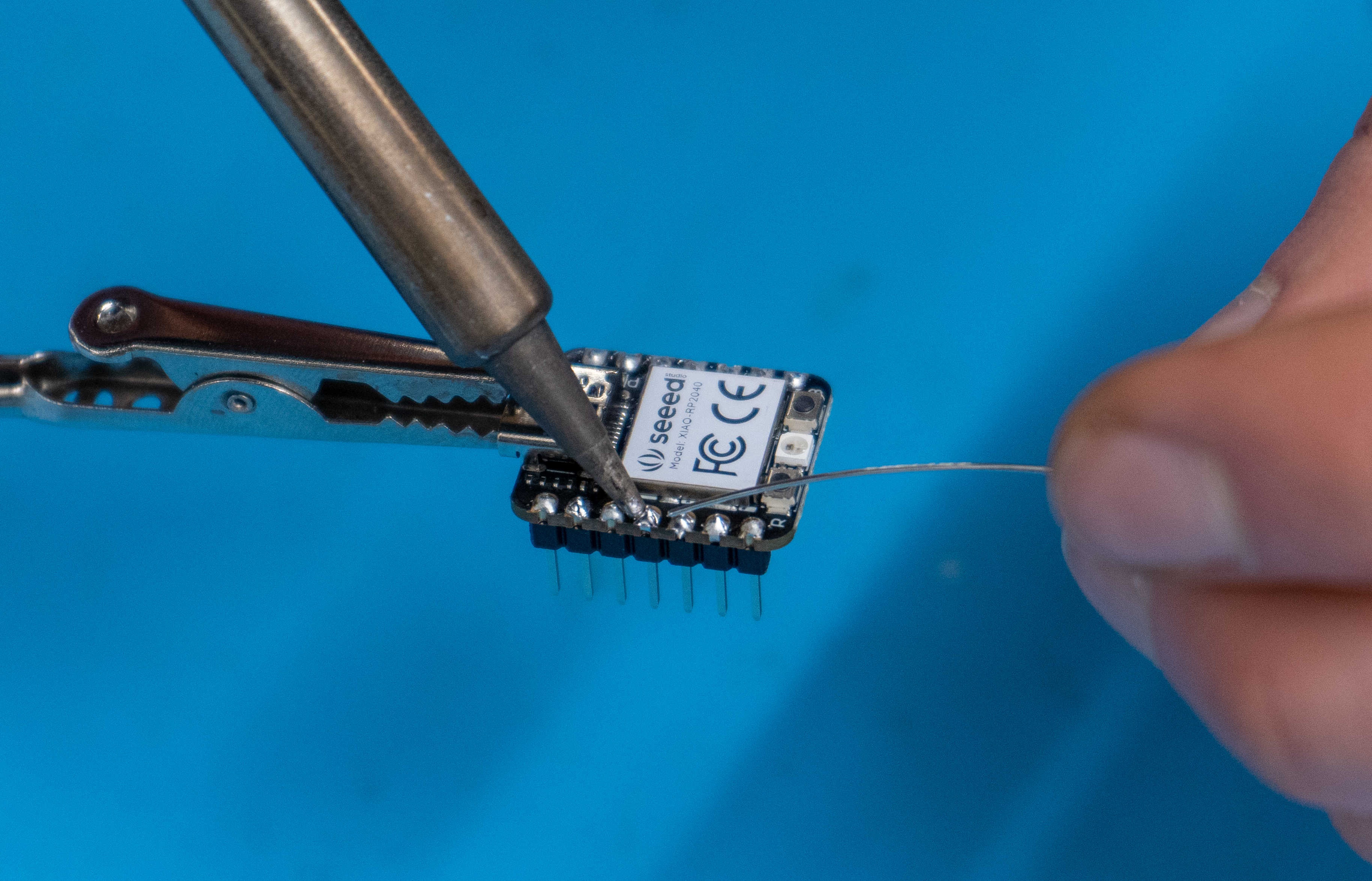
With the switches, plate, and PCB squashed into one piece, it's now time to begin soldering. You'll most likely want to install the smallest, pointiest soldering tip available. Turn on the soldering iron and wait for it to heat up completely. You'll know it's ready to go when the green LED on the housing starts blinking rapidly. The temperature dial on the soldering iron should be set to about 700 degrees Fahrenheit. Solder each of the pins on the key-switches. (there are 8x2 = 16 of them). You should aim to create a nice and smooth conical joint with not-too-much and not-too-little solder. Take your time, and if you make a joint you don't like, use the solder wicking braid to clean it up and try again.

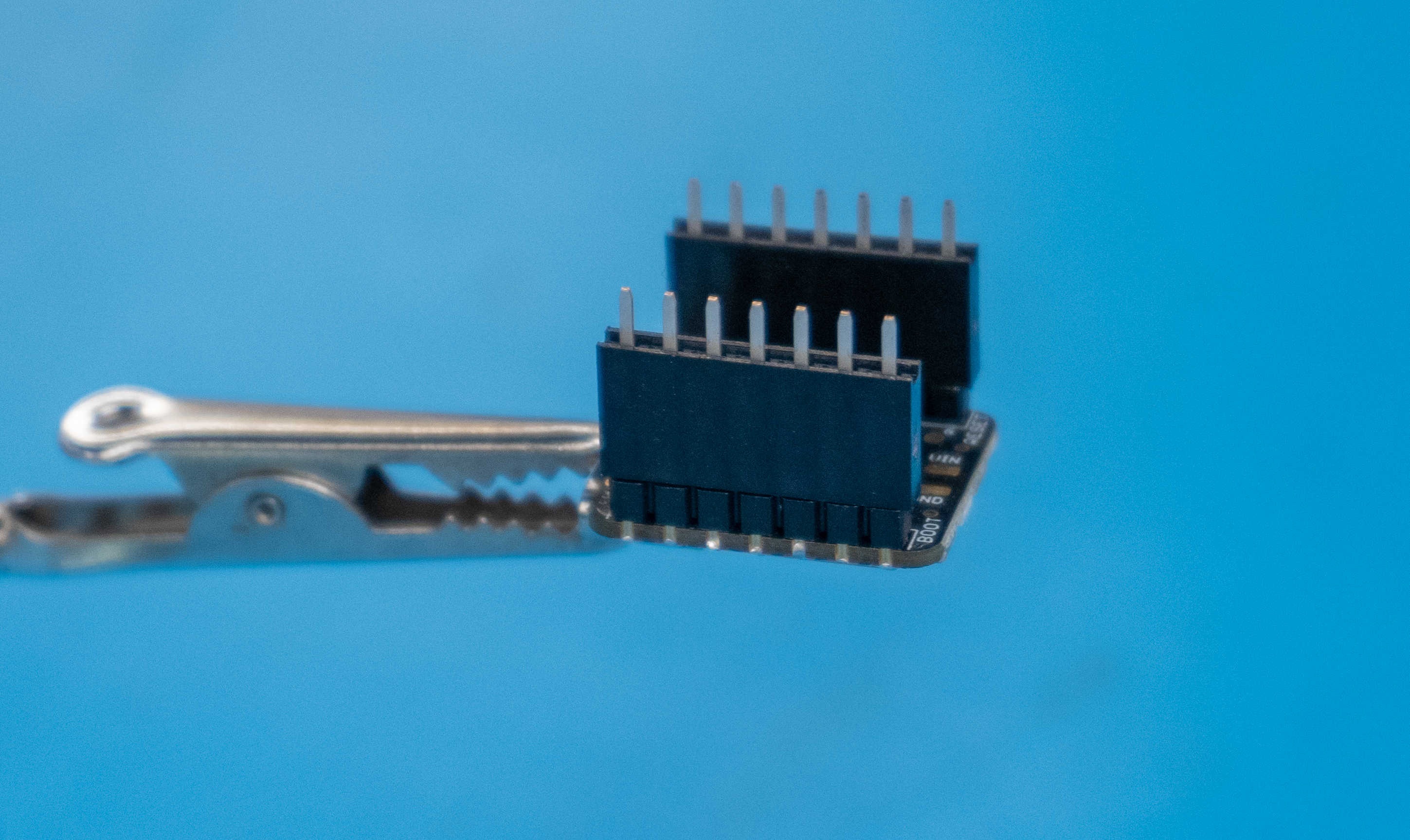
Next, you'll need to prep the micro-controller (MCU) for assembly. Take it out of it's package and push the pin headers into the two rows of holes in the board. The shorter leads on the pin headers go up into the micro-controller, and the longer sets of leads stick down to connect to the other parts of the assembly. Solder each of the leads on the pin headers to the MCU. We aren't connecting most of the pins to anything electrically, but soldering them all adds a bit of mechanical strength.
Next, push the pin header sockets into the exposed header side on the MCU.
Slot the entire MCU sub-assembly through the acrylic plate and into the PCB (facing upwards, like the switches) and solder the sockets of the MCU and the key switches to the main PCB.
Important
Don't solder the micro-controller directly to the main PCB. You won't be able to access one of the mounting holes needed to hold the PCB assembly into the case!
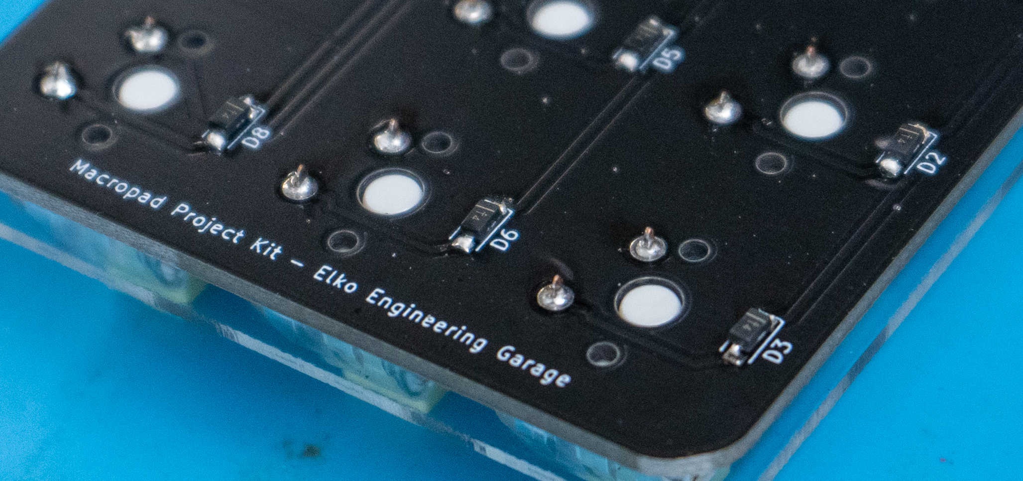
The final components we need to solder are the diodes. They are supplied to us in a surface-mount-technology (SMT) form factor. This style of component is extremely common in newish electronics, because they are smaller and cheaper. For assembly by hand, however, they are slightly more challenging to solder. Note that the diodes also have a polarity, so you'll need to orient the small white mark on each component to the side indicated by the text on the PCB. Soldering up all 8 diodes will be a bit of a challenge, but it's a great way to build your soldering skills. A few extra diodes are included in the kit in case you misplace one. Our suggested technique for soldering SMT components is as follows:
- Add a small blob of solder to one of the pads of the footprint on the PCB
- With the tip of the soldering iron keeping the blob you just created, hold the component in your other hand with a pair of tweezers and slide it into the correct position.
- Remove the tip of the soldering iron from the molten pool of solder. Once the metal freezes, the component will be held in place by one pad.
- Now that the component is locked into position, you can use both hands to solder up the other pads much more easily
- Done!
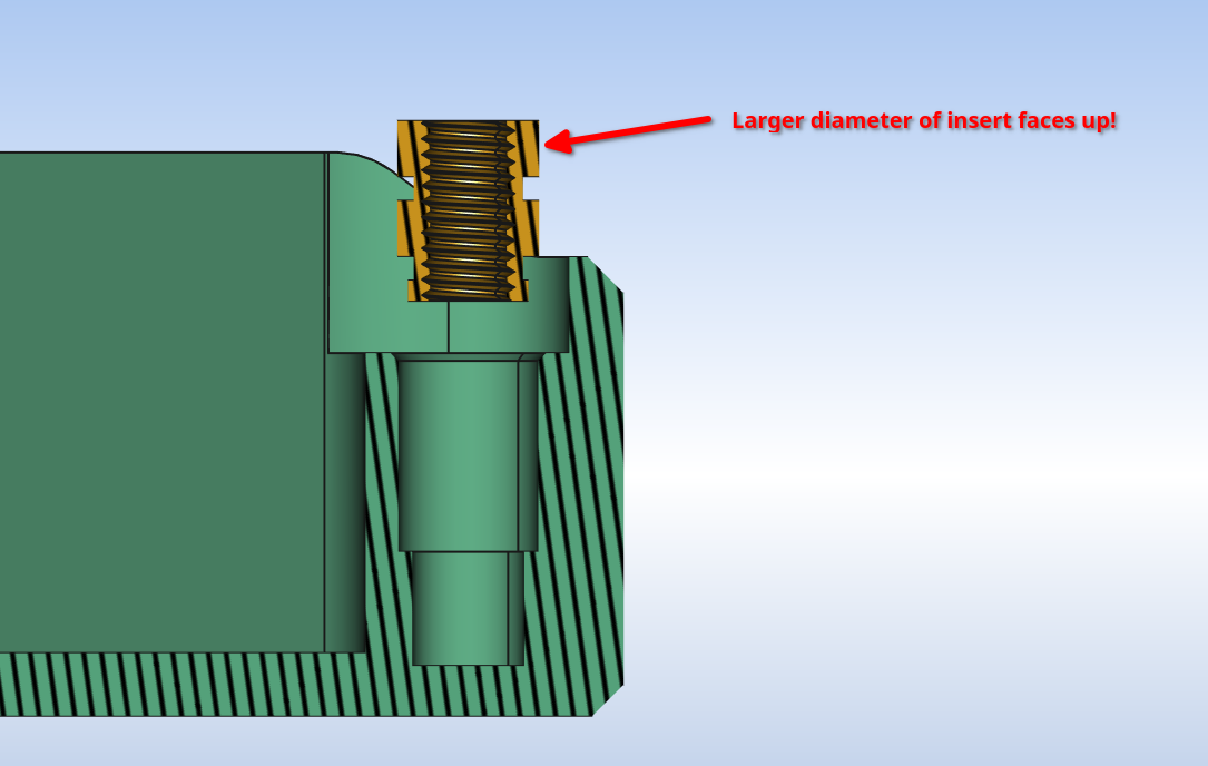
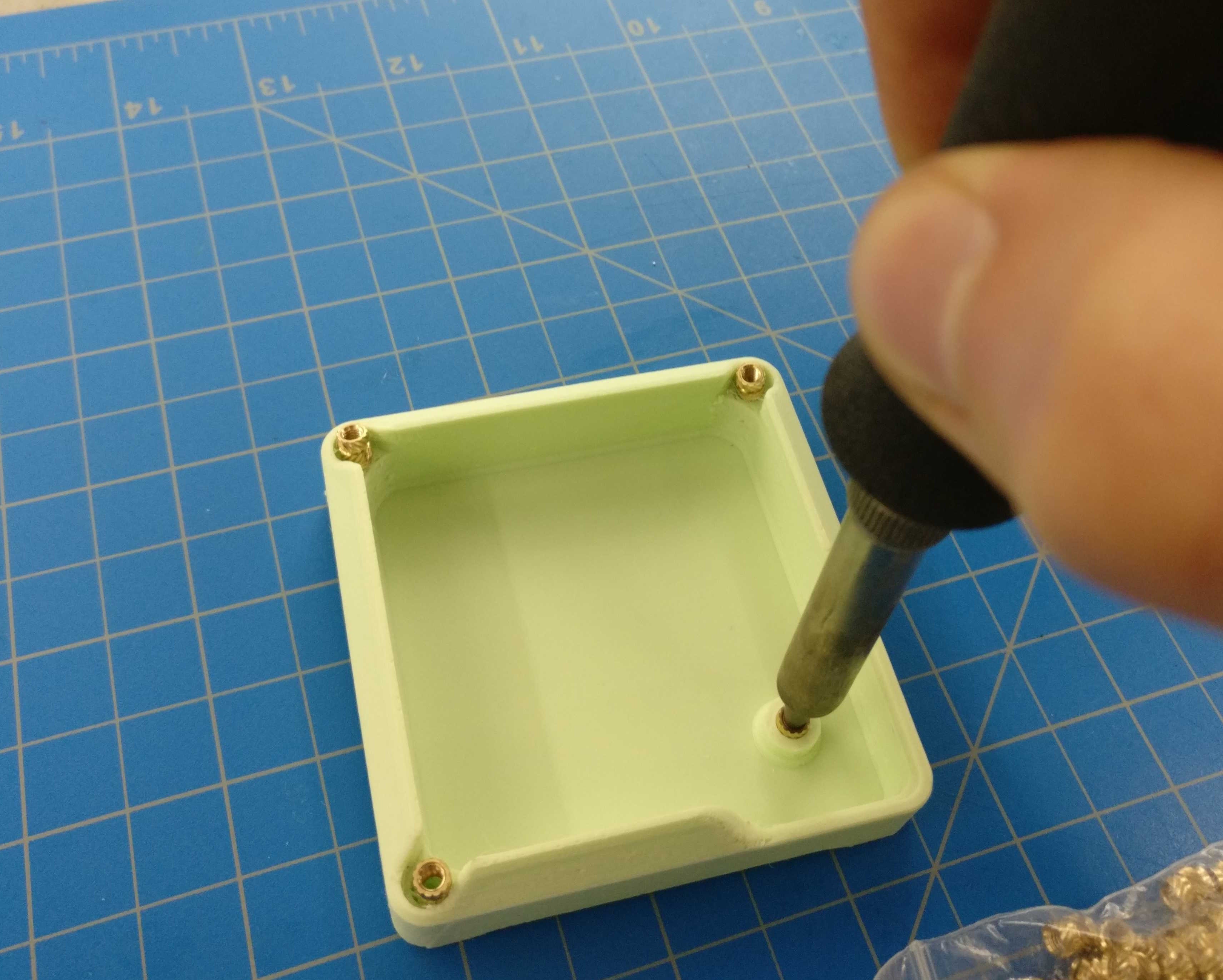
While you are at the soldering iron station, use the iron tip to press the heat-set inserts into the 3D-printed plastic case. All of the brass inserts should be pushed in from the top side, and should be inserted until they are just flush with the surface of the 3D print. Do this step carefully, making sure not to melt too much of the plastic.
You can now use the M3 screws included in the project kit to fasten the switch assembly to the case. Note that you’ll need to pull the micro-controller assembly off of the pin sockets to access the screw underneath. You'll then be ready to move on to the next step!
Step 4: Programming the board
Time to complete: 15-30 minutes.
Connect a USB type-C cable to the MCU. Then, press and hold the small 'boot' button on the board, while simultaneously plugging in the other end of the USB cable to your computer.
Go to your File Explorer, and you should be able to access the internal storage of the MCU as if it were a USB thumb-drive. You should see a folder called 'RPI-RP2' or something similar. It should contain two files, called "INDEX" and "INFO_UF2".
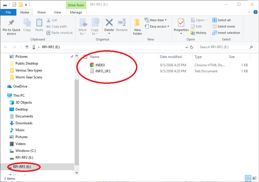
Delete the existing files, and copy the following .uf2 firmware file to the MCU storage.
 adafruit-circuitpython-seeeduino_xiao_rp2040-en_US-8.1.0.uf2
The micro-controller should immediately recognize the new firmware, and automatically reboot itself. It will now appear in your file explorer as a device called 'CIRCUITPY'.
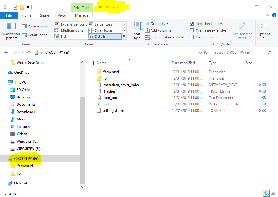
Delete the file 'code.py' file and the 'lib' folder. Copy the contents of the following zip file (a new 'code.py' and 'lib' folder) into the MCU storage.
Important
Make sure to extract the files before you copy them. Just putting the zipped folder into the micro-controller storage won't do anything useful!
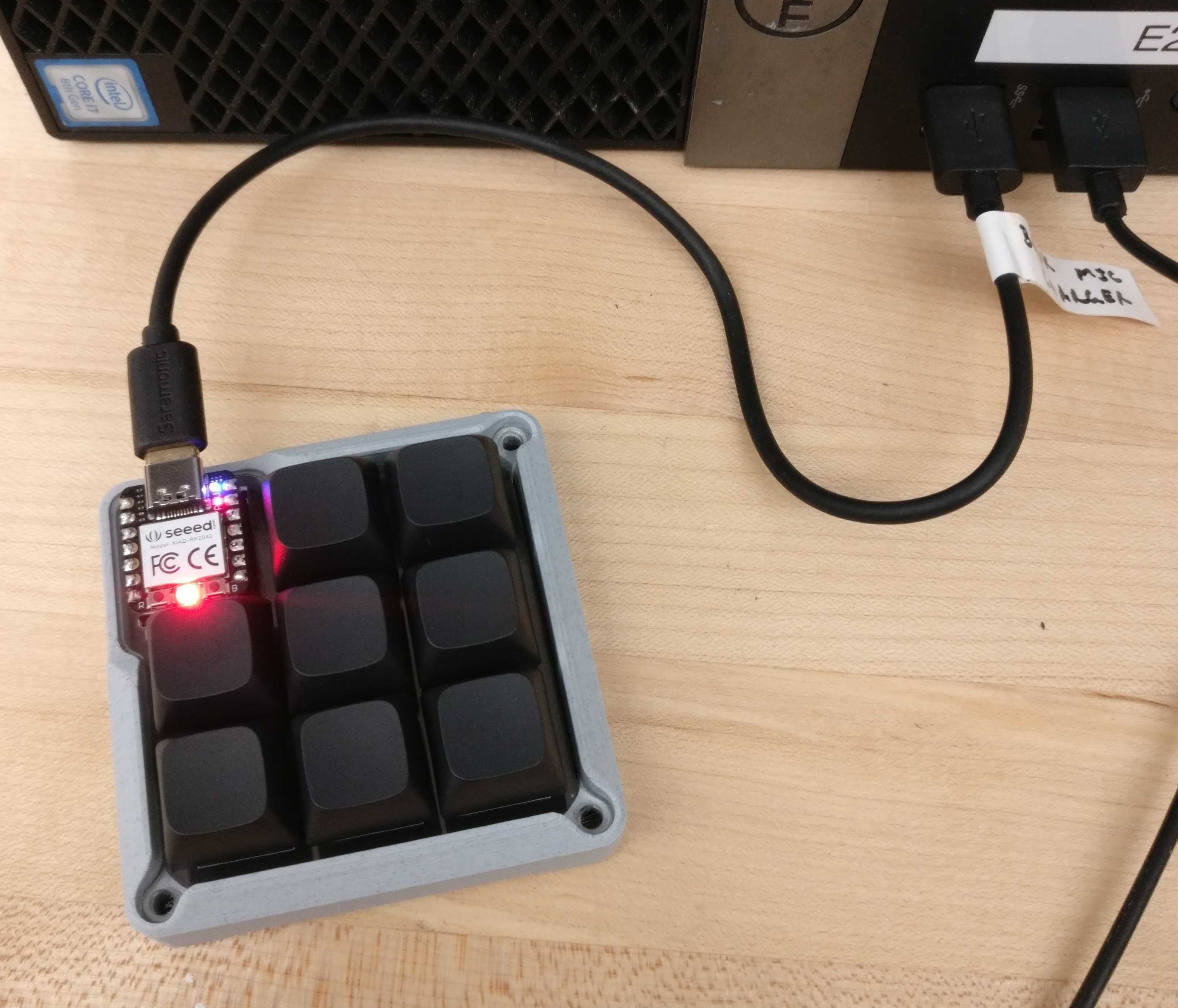
Next, unplug the macro-pad from your PC or laptop, then plug it back in. The on-board LED should flash yellow four times. If it flashes red, some kind of error occurred. In that case, try re-copying the code files onto the board.
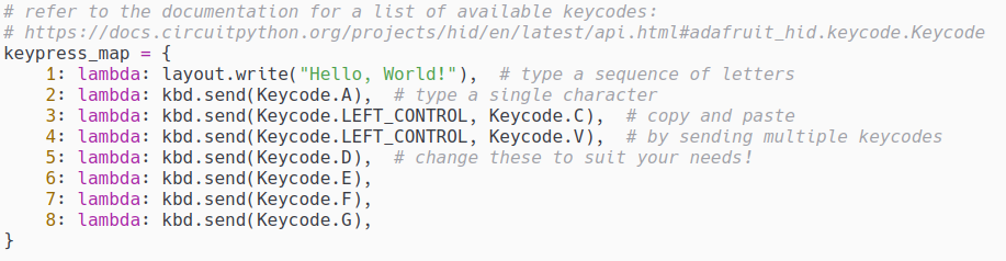
You can now test out the keypad! If any of the keys don't work, check your soldering for missed or broken connections. You can also edit the pressed key that the macro-pad will send by changing the 'keypress_map' variable in the 'code.py' file using a text editor. The key numbering is as follows:
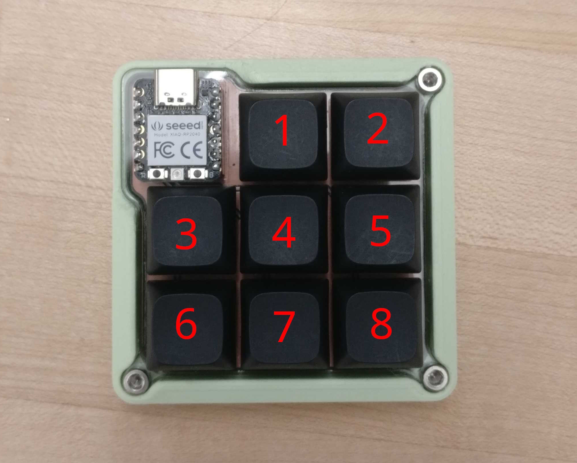
You should now have a finished macro-pad. You can change the key configurations to make it easier to use your favorite CAD software, or add some hotkeys for gaming and productivity. If you want to make your macro-pad even cooler, check out the appendix for some ideas on using different materials and manufacturing processes for the case and other parts. If you have feedback about the project, or want to add your completed macro-pad to the Garage Makes display, send us an email. Thanks for completing this project!
Appendix: Project Modification Ideas
Some of the parts of the macro-pad can be constructed in different ways than the ones described in these instructions:
Case:
- CNC machine it, either from wood using the CNC router, or from metal/plastic using the CNC mills.
- Use the resin (SLA) printers to print a translucent case with a very smooth finish.
Acrylic Plate
- Cut it out of a thin sheet of wood veneer using the CO2 laser cutters.
- Make it out of metal sheet with the fiber laser.
- Make a plastic or carbon fiber plate using the water-jet cutter.
Key Caps & Key Switches
- Use the vinyl cutter to make labels for the key caps.
- Print your own key caps using the resin (SLA) printers.
PCB
- Use the PCB mill to make your own PCB - This will be a particularly challenging modification!
Micro-controller
- Install QMK firmware to gain access to more complex key bindings.
Here are the solid models and PCB design files - They may be useful to you if you attempt to make modifications to this project:
macropad_assembly.stepmacropad_case.step kicad_project_files.zip